- 您现在的位置:买卖IC网 > Sheet目录1991 > CS4362-KQZ (Cirrus Logic Inc)IC DAC 6CH 114DB 192KHZ 48LQFP
DS257F2
11
CS4362
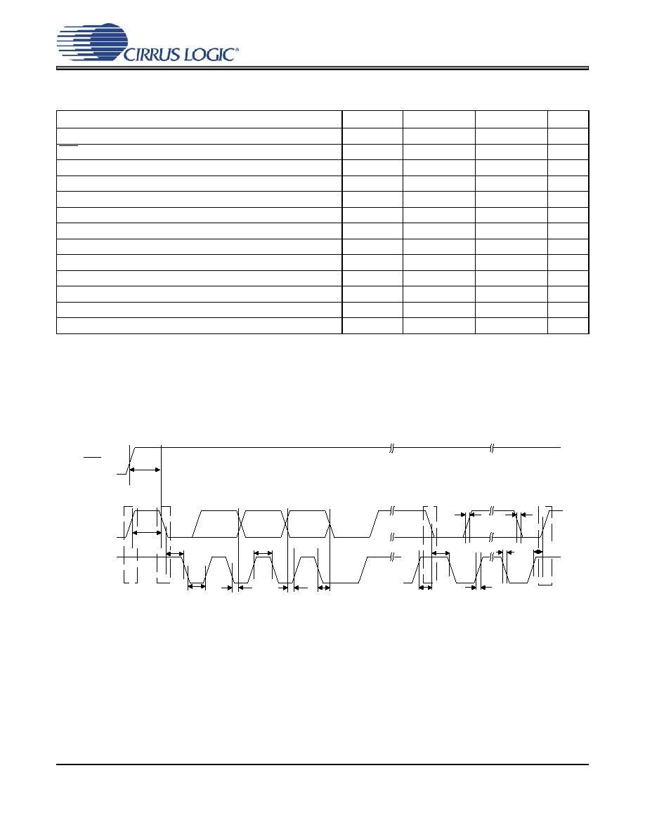
SWITCHING CHARACTERISTICS - CONTROL PORT - IC FORMAT
(For KQZ TA = -10°C to +70°C; VLC = 1.8 V to 5.5 V; Inputs: Logic 0 = GND, Logic 1 = VLC, CL =30pF)
Notes:
19. Data must be held for sufficient time to bridge the transition time, tfc, of SCL.
20. The acknowledge delay is based on MCLK and can limit the maximum transaction speed.
21.
for Single-Speed Mode,
for Double-Speed Mode,
for Quad-Speed Mode.
Parameter
Symbol
Min
Max
Unit
SCL Clock Frequency
fscl
-
100
kHz
RST Rising Edge to Start
tirs
500
-
ns
Bus Free Time Between Transmissions
tbuf
4.7
-
s
Start Condition Hold Time (prior to first clock pulse)
thdst
4.0
-
s
Clock Low time
tlow
4.7
-
s
Clock High Time
thigh
4.0
-
s
Setup Time for Repeated Start Condition
tsust
4.7
-
s
SDA Hold Time from SCL Falling
thdd
0-
s
SDA Setup time to SCL Rising
tsud
250
-
ns
Rise Time of SCL and SDA
trc, trc
-1
s
Fall Time SCL and SDA
tfc, tfc
-
300
ns
Setup Time for Stop Condition
tsusp
4.7
-
s
Acknowledge Delay from SCL Falling
tack
-
ns
15
256
Fs
×
---------------------
15
128
Fs
×
---------------------
15
64
Fs
×
------------------
t buf
t
hdst
t
lo w
t
hdd
t
high
t sud
Stop
S t a rt
SD A
SC L
t
irs
RS T
t
hdst
t
rc
t
fc
t sust
t susp
St a rt
Stop
R epe a t e d
t
rd
t
fd
t ack
Figure 3. Control Port Timing - IC Format
发布紧急采购,3分钟左右您将得到回复。
相关PDF资料
CS4362A-DQZ
IC DAC 6CH 114DB 192KHZ 48-LQFP
CS4364-CQZR
IC DAC 103DB 24BIT 6CH 48-LQFP
CS4382A-DQZ
IC DAC 8CH 114DB 192KHZ 48-LQFP
CS4384-CQZR
IC DAC 8CH 103DB 192KHZ 48-LQFP
CS4385-DQZR
IC DAC 8CH 114DB 192KHZ 48-LQFP
CS4391A-KZZR
IC DAC 24BIT 192KHZ W/VC 20TSSOP
CS4392-KZZ
IC DAC 24BIT 192KHZ W/VC 20TSSOP
CS4397-KSZ
IC DAC 24BIT MULTY STNDRD 28SOIC
相关代理商/技术参数
CS4362-KQZR
功能描述:数模转换器- DAC IC 114dB 192kHz 6Ch DAC RoHS:否 制造商:Texas Instruments 转换器数量:1 DAC 输出端数量:1 转换速率:2 MSPs 分辨率:16 bit 接口类型:QSPI, SPI, Serial (3-Wire, Microwire) 稳定时间:1 us 最大工作温度:+ 85 C 安装风格:SMD/SMT 封装 / 箱体:SOIC-14 封装:Tube
CS4364
制造商:CIRRUS 制造商全称:Cirrus Logic 功能描述:103 dB, 192 kHz 6-Channel D/A Converter
CS4364_08
制造商:CIRRUS 制造商全称:Cirrus Logic 功能描述:103 dB, 192 kHz 6-Channel D/A Converter
CS4364-CQZ
功能描述:数模转换器- DAC IC 24bit 6Chn DAC w/ DSD Supt&Lw-Ltnc DF RoHS:否 制造商:Texas Instruments 转换器数量:1 DAC 输出端数量:1 转换速率:2 MSPs 分辨率:16 bit 接口类型:QSPI, SPI, Serial (3-Wire, Microwire) 稳定时间:1 us 最大工作温度:+ 85 C 安装风格:SMD/SMT 封装 / 箱体:SOIC-14 封装:Tube
CS4364-CQZR
功能描述:数模转换器- DAC IC 24b 6Ch DAC w/DSD Supt/Lw-Ltnc DF RoHS:否 制造商:Texas Instruments 转换器数量:1 DAC 输出端数量:1 转换速率:2 MSPs 分辨率:16 bit 接口类型:QSPI, SPI, Serial (3-Wire, Microwire) 稳定时间:1 us 最大工作温度:+ 85 C 安装风格:SMD/SMT 封装 / 箱体:SOIC-14 封装:Tube
CS4364-DQZ
制造商:CIRRUS 制造商全称:Cirrus Logic 功能描述:103 dB, 192 kHz 6-Channel D/A Converter
CS4364-DQZR
制造商:CIRRUS 制造商全称:Cirrus Logic 功能描述:103 dB, 192 kHz 6-Channel D/A Converter
CS4365
制造商:CIRRUS 制造商全称:Cirrus Logic 功能描述:114 dB, 192 kHz 6-Channel D/A Converter